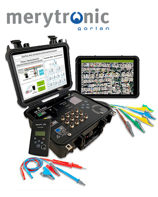
低壓帶電電網相位與饋線識別器
掌握電網拓撲資料,對於妥善管理配電網路至關重要。因此,必須清楚了解每一項低壓電網設備/用戶的連接方式與位置,也就是確認各設備/用戶分別連接至哪一台變壓器、哪一條饋線,以及哪一個相位。
將這些資訊應用於地理資訊系統 (GIS) 解決方案中,可用於計算變壓器負載平衡、分析故障、規劃預防性維護作業等,最終確保供電品質。
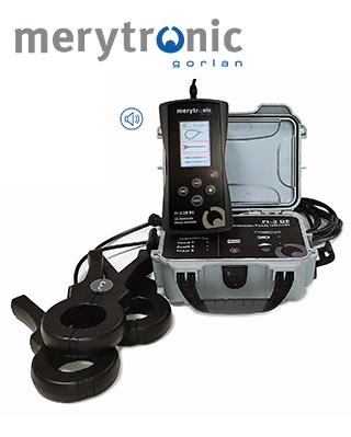
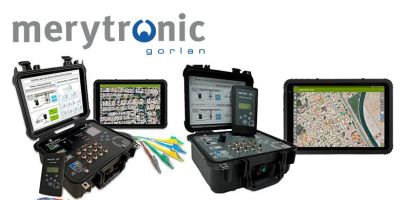
Merytronic 推出新一代相位與饋線識別器 ILF G2 及 ILF G2 Pro,可識別變壓器輸出端的三個相位及最多 12 條饋線。這兩款設備專為大規模電網測繪作業而設計,最多可同時處理 99 座變壓器配電站。
透過 ARIADNA Grid 開發的 GridGIS Connect 應用程式,可加快資料的蒐集、儲存,以及傳輸至電力公司的 GIS 系統。如此一來,電網拓撲數位化測繪作業所需時間更短,拓撲資料也能更快速且正確地整合至電力公司的 GIS 系統中。
主要特點
- 可在線運作,無須將電網停電。
- 可識別用戶所連接的三個相位之一,以及最多 12 條饋線中的所屬饋線。
- 專為大規模電網測繪作業而設計。
- 可在數秒內完成識別。
- 最多可同時處理 99 座變壓器配電站。
- 已驗證可在電纜距離超過 1 km 的情況下有效運作。
- 適用於各種低壓電網配置,包括三角形接線 (Delta)、星形接線(無中性線)、耦合及/或環狀網路、串接配置;相間電壓最高可達 480 VAC,頻率為 50 或 60 Hz。
- ILF G2 Pro 可用於串接式配電網路配置,最多支援 4 個電氣層級,並可包含多個饋線分接箱。
- 單一操作人員即可輕鬆使用。
- 線路裝置 (Line Device) 內建藍牙功能。
- 配備 GridGIS Connect 應用程式,可蒐集、儲存及傳輸資料,並與 GIS 系統相容。
- 中央裝置 (Central Device) 支援多組現場作業團隊,進行同一座變壓器配電站的測繪作業。
GridGIS D-twin應用程式
為了有效管理配電網路,必須準確掌握低壓配電網路的拓撲結構,並確保相關資訊維持最新狀態。
GridGIS D-twin 數位化應用程式是專為搭配 ILF G2 | ILF G2 Pro 設備進行現場作業而開發。
此應用程式由 Ariadna Grid開發,可自動儲存電表與二次變電站之間的對應關係,以及電表所連接的饋線編號與相位編號。
透過此應用程式,現場蒐集的資料可顯示於作業區域的地圖上,讓使用者快速且輕鬆地查看相關資訊。
應用程式特點
- 二次變電站資產登錄:包含二次變電站識別碼、變壓器、低壓配電盤、饋線編號、中壓與低壓電纜類型、中壓開關設備等資訊。
- 設備配置記錄:包含中央單元代碼、饋線編號與 Rogowski 感測器輸入編號之間的對應關係等資訊。
- 拓撲/連接關係:記錄透過線路單元識別的電表資訊,包括二次變電站、饋線、相位,以及日期、時間與操作人員。
- 每項已識別資產的照片記錄。
- 每項已識別資產的 GPS 地理定位:包含二次變電站、電表箱、電線桿、電表等。
- 追蹤作業進度。
- 藍牙連線。
- 匯出/匯入與 GIS 工具相容的檔案:GeoJSON、KMZ 及 Shapefile。
- 與電力公司的 GIS 系統整合資料。
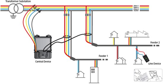
操作示意圖
*規格如有變更,恕不另行通知。
Central Device (CD)
|
尺寸 (mm) |
343 × 327 × 152 |
|
防護等級 |
IP65 |
|
重量 |
4 kg |
|
相間電壓 (V Phase-Phase) |
220 – 480 Vac |
|
相對中性線電壓 (V Phase-Neutral) |
130 – 280 Vac |
|
最大連接電壓 (Vmax connection) |
480 Vac |
|
頻率 |
50/60 Hz |
|
最大電流 |
0.35 – 0.40 A |
|
短路保護 |
4 A 6.3 × 32 mm T 型保險絲 |
|
操作溫度 |
-20 / 60 ºC |
|
藍牙工作頻段 |
2.402 – 2.480 GHz |
|
藍牙輸出功率 |
+1.5 dBm |
Line Device (LD)
|
尺寸 (mm) |
120 × 220 × 65 |
|
防護等級 |
IP54 |
|
重量 |
0.75 kg |
|
相對中性線電壓 (V Phase-Neutral) |
90 – 265 Vac |
|
最大電壓 |
480 Vac |
|
電源 |
4×1.5 V 3號電池 (6 VDC) |
|
頻率 |
50/60 Hz |
|
短路保護 |
16 A 6.3×32 mm F型保險絲 |
|
操作溫度 |
-10 / 55 ºC |
|
藍牙工作頻段 |
2.402 – 2.480 GHz |
|
藍牙輸出功率 |
+1.5 dBm |
符合標準
安全標準︰IEC 61010-1:2010/EN 61010-1:2010/ UNE-EN 61010-1:2011; IEC 61010-2-030:2010/ UNE-EN 61010-2-030:2011; IEC 60950-1:2005 / EN 60950-2006 / UNE-EN 60950-1:2007.
電磁相容性標準︰IEC 61326-1:2012/ UNE EN 61326-1:2013, ETSI EN 301489-1 vl.9.2 (2011-09), ETSI EN 301489-1 V2.2.1, ETSI EN 301489-17 v3.1.1 (2017-02); UNE-EN 61000-3-2:2014; UNE-EN 61000-3-3:2013; UNE-EN 61000-4-2:2009; UNE-EN 61000-4-3:2006; UNE-EN 61000-4-4; UNE-EN 61000-4-5; UNE-EN 61000-4-6; UNE-EN 61000-4-11; UNE-EN 55032:2015
無線電標準︰IEC 62479:2010 / UNE EN 62479:2011
It results critical to know the network topology data in order to maintain a correct management of electrical distribution networks. Therefore, it´s essential to know HOW and WHERE each of the LV assets/consumers are connected, to which transformer-feeder-phase.
The use of this information in a GIS solution allows calculation of transformer load balances, faults, preventive maintenance task planning, etc., and at end, guarantees the quality of electrical supply.
Merytronic has designed the new generation of Phase and Feeder identifiers ILF G2 and ILF G2 Pro, which can identify 3 phases and up to 12 feeders of a transformer output. They are designed for big mapping campaigns, up to 99 Transformer Substations simultaneously.
Thanks to its app GridGIS Connect (develop by ARIADNA Grid) speeds up collection, storage and transfer data to utility’s GIS system. The network topology digitalization campaigns result shorter and the integration of topology data into utility’s GIS system faster and without mistakes.
Main features
- Works in service, without de-energizing the network
- Identify to which of the three phases and up to 12 feeders the consumers are connected
- Designed for big mapping campaigns
- Identification is done a few seconds
- Up to 99 Transformer Substation simultaneously
- Proved efficiency on cable distances > 1 km.
- Suitable for any Low Voltage Network configurations: Delta, Star (no neutral), coupled and/or ringed networks, cascade arrangement, up to 480 Vac between Ph-Ph and 50 or 60 Hz.
- ILF G2 Pro available for cascade arrangement of distribution networks (with several feeder pillars up to 4 electrical levels)
- A single operator can easily use it.
- Line Device with integrated Bluetooth
- GridGIS Connect app for collect, storage and transfer data (compatible with GIS system).
- Multiple field-work crews for each Transformer Substation (Central Device)
GridGIS D-twin app
For an efficient management of distribution networks, it is essential to have an accurate and up-to-date knowledge of the low-voltage network topology.
The GridGIS D-twin digitising app is specially developed for field work with the ILF G2 | ILF G2 Pro devices.
Developed by Ariadna Grid (our technical partner), it automatically stores the results of the correspondence between the meter and the Secondary Substation, with the feeder and phase number to which it is connected.
Through this application the data capture is displayed on a map of the work area, quickly and easily.
App features
- Secondary Substation (SS) asset register: SS identifier, transformer, LV panel, feeder numbers, type of MV and LV cables, MV switchgear, etc.
- Recording of the device configuration: Central Unit code, correspondence between feeder number and Rogowski sensor input number…
- Topology/CONNECTIVITY: logging of the energy meter identification with the Line Unit: Secondary Substation – feeder – phase + date – time + operator.
- Photo of each identified asset
- GPS geolocalization of each identified asset: SS, meter boxes, pole, meter…
- Track work progress
- Bluetooth connection
- Export/Import in files compatible with GIS tools: GeoJSON, KMZ and Shapefile
- Data integration with the utility’s GIS system
How to convert the ILF G2 into a Cable Identifier>
Demo: visualisation of topological information>
Operational diagram
*Specifications subject to change without notice
Central Device (CD)
|
Size (mm) |
343 × 327 × 152 |
|
Protection |
IP65 |
|
Weight |
4 kg |
|
V Phase-Phase |
220 – 480 Vac |
|
V Phase-Neutral |
130 – 280 Vac |
|
Vmax connection |
480 Vac |
|
Frequency |
50/60 Hz |
|
Imax |
0.35 – 0.40 A |
|
Short Circuit protection |
4 A 6.3×32 mm T fuse |
|
Operating Temperature |
-20 / 60 ºC |
|
Bluetooth frequency band operation |
2.402 – 2.480 GHz |
|
Bluetooth output power |
+1.5 dBm |
Line Device (LD)
|
Size (mm) |
120 × 220 × 65 |
|
Protection |
IP54 |
|
Weight |
0.75 kg |
|
V Phase-Neutral |
90 – 265 Vac |
|
Vmax |
480 Vac |
|
Power supply |
4×1.5 V AA (6 VDC) |
|
Frequency |
50/60 Hz |
|
Short Circuit protection |
16 A 6.3×32 mm F fuse |
|
Operating Temperature |
-10 / 55 ºC |
|
Bluetooth frequency band operation |
2.402 – 2.480 GHz |
|
Bluetooth output power |
+1.5 dBm |
Compliance standards
Safety standards: IEC 61010-1:2010/EN 61010-1:2010/ UNE-EN 61010-1:2011; IEC 61010-2-030:2010/ UNE-EN 61010-2-030:2011; IEC 60950-1:2005 / EN 60950-2006 / UNE-EN 60950-1:2007.
EMC standards: IEC 61326-1:2012/ UNE EN 61326-1:2013, ETSI EN 301489-1 vl.9.2 (2011-09), ETSI EN 301489-1 V2.2.1, ETSI EN 301489-17 v3.1.1 (2017-02); UNE-EN 61000-3-2:2014; UNE-EN 61000-3-3:2013; UNE-EN 61000-4-2:2009; UNE-EN 61000-4-3:2006; UNE-EN 61000-4-4; UNE-EN 61000-4-5; UNE-EN 61000-4-6; UNE-EN 61000-4-11; UNE-EN 55032:2015
RF standards: IEC 62479:2010 / UNE EN 62479:2011